Is It Easy to Work on M3 Self
What are self-tapping screws for plastics?
Self-tapping screws for plastics, as the name implies, form or tap its threads when screwed into the plastic material with either pre-drilled or moulded pilot holes. These provide an economical method of joining two plastics or metal to plastic and allow easy disassembly and reassembly.
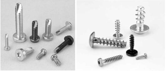
These self-tapping screws are excellent choices, especially in injection moulding parts, as it is much cheaper to mould pilot holes than either threaded holes or have threaded inserts. These special fasteners are used instead of standard fasteners due to their narrow thread profile, increased pull out resistance and lower radial stress. The lower radial stress also prevents boss damage.
They are commonly mistaken for self-drilling screws. Standard self-drilling screws have a drilling tip at the end of the screw, which helps form a thread without a pilot hole. They are used predominantly in sheet metal, soft metal and wood to drill, tap and fasten the screw in one step.
How does self-tapping screw for plastic work?
How do Self-tapping screws for plastic differ from standard screws?
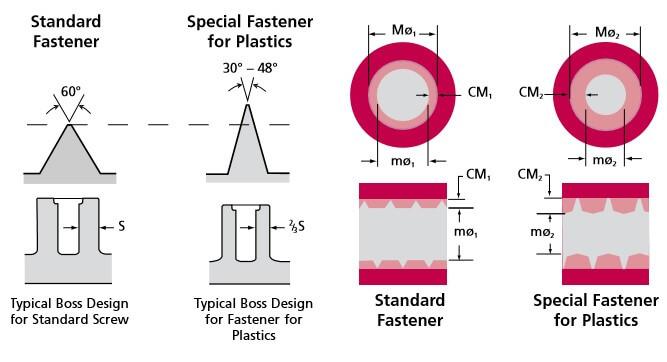
Thread profile angles also called a flank angle of self-tapping screws, are smaller than standard screws, as shown in the figure below, which reduces the internal radial stresses created during the removal and deformation of plastic.
As the root diameter is smaller than a standard fastener, the thread engagement (CM) is diametrically more than the standard fastener, which increases the holding power on soft plastic compared to metal.
Types of self-tapping screws
Selecting the most appropriate fastener to suit the material would allow thinner bosses and avoid special mould inserts and locking components, which will reduce the overall engineering product cost. These will also reduce plastic material usage, shot time and the cost of injection moulding parts.
Self-tapping screws are grouped under two groups viz.: thread forming and thread cutting. The selection of screw-type will depend on its application requirement, material type and properties. There are a lot of trademarked and patent designs from various companies such as Stanley, EPOK, TR fasteners etc. All the manufacturers have options with different thread profile angles (30-45-48 degrees) to suit the range of flexural modulus of plastics.
Thread forming
Thread forming screws for plastic doesn't have a pointed tip and would need a pilot hole. Screw thread deforms the plastic material to flow around the screw threads. Hence the overlapping amount (thread engagement) and thread profile angle are crucial.
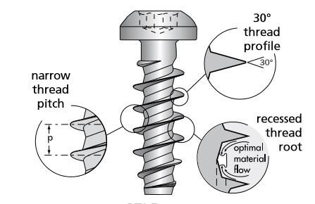
Thread forming screws creates high internal stresses because the material is deformed rather than removed. As a result, these screws can only be utilised in soft polymers with lower flexural modulus.
Thread cutting
Thread cutting screws for plastics, also known as a thread tapping screws, has a sharp cutting edge that cuts plastic when they are screwed into the pilot hole, forming a threaded joint. This produce reduced internal stresses compared to thread forming screws, making them suitable for stiffer plastic material with higher flexural modulus.
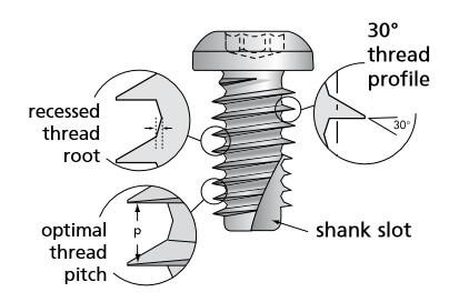
It is important to have the correct pilot hole diameter and depth. Hole depth has to be deeper than the screw engagement length to allow space for the removed material to move. For fibre or glass-filled plastics, these provide high thread engagement, high clamp loads & reduced stress. The biggest drawback of the thread cutting screw is thread stripping during disassembly.
Advantages and Disadvantages of using self-tapping screws for plastic
Advantages
-
- Self-tapping screws for plastic joining is reliable if used properly
- They are cheap compared to other means of joining
- Easily disassembled
- It doesn't require pre-moulded threads
- Good impact and vibration resistance
- No curing time or settling time to achieve full strength
- No special tool required
Disadvantages
-
- Only up to 10 disassembly and reassembly cycles
- Stress concentration or raiser is likely
- Very difficult to manage the tightening torque
- Increases the part count
- It might affect the aesthetics of the end product
Design guide for self-tapping screw joints for plastics
Plastic opens up great opportunities for engineering product designers due to its versatility and material options. But when it comes to joining plastics together or plastics to another material, it also poses some unique problems such as using fasteners and threads.
Standard screws and self-tapping screws for metal such as type A and type AB are not suitable for plastic because of their wide flank angle and shallow threads. They are used on sheet metal and thick plastic sheets like UPVC frames. As discussed in the section above, the two types of self-tapping screws available to use on most common plastics are thread forming and thread cutting screws.
Every type of plastic has unique performance difficulties, such as ductility, thermal expansion, and clamp retention. Choosing a fastener that best meets these characteristics is essential to a successful screw joint in your product designs.
With so many polymer types available, it's always best to test your screw joint to find the best screw type and design. Choosing the correct fastener designed for a specific material type would give
-
-
- Higher strip out torques
- Increase resistance to loosening
- Higher pull-out values
-
Self-tapping screw for plastic design factors
Self-tapping screw joint effectiveness depends on the following factors
-
-
- Plastic material properties
- Type of screws
- Fastener interface design
-
Plastic material properties
The self-tapping plastic screw joint performance is affected by the following plastic properties.
-
-
- Material stiffness (Flexural modulus of plastic)
- Additives and fillers (Filler, reinforcement content and type)
- Thermal expansion rate
- Creep rate
-
Material stiffness – Flexural modulus of plastics
Flexural modulus or bending modulus measures the stiffness of the plastic during the initial step of the bending and deforming process and is the stress to strain ratio in flexural deformation. In simple terms, plastics' tendency to resist bending.
| Materials | Flexural Modulus (psi) | Flexural Modulus (MPa) | ||
|---|---|---|---|---|
| Thermoplastics | Ductile | Polyethylene (PE) | 150000 | 1034 |
| Polypropylene (PP) | 200000 | 1379 | ||
| Polycarbonate (PC) | 340000 | 2344 | ||
| ABS, 0-20% glass fill | 350000 | 2413 | ||
| Polyamide 66 (PA) | 350000 | 2413 | ||
| Acetal (AC) | 400000 | 2758 | ||
| Polystyrene (PS) | 430000 | 2965 | ||
| Polypropylene, 40% talc fill (PP40) | 500000 | 3447 | ||
| Polyphenylene Sulfide | 550000 | 3792 | ||
| Moderate | ABS, 20% glass fill | 650000 | 4482 | |
| Polyamide 66, 12% glass fill | 800000 | 5516 | ||
| Polycarbonate, 20% glass fill (PC20) | 850000 | 5861 | ||
| Stiff | Polycarbonate, 30% glass fill (PC30) | 1100000 | 7584 | |
| Polybutylene Terephthalates 30% glass fill (PBT30) | 1100000 | 7584 | ||
| Polyamide 66, 30% glass fill (PA30) | 1200000 | 8274 | ||
| Liquid Crystal Polymer (LCP) | 1400000 | 9653 | ||
| Thermosets | Polyphenylene Sulfide, 40% fill (PPS40) | 1700000 | 11721 | |
| Phenolic, 20% glass fill | 1750000 | 12066 | ||
| Polyester, 50% glass fill | 2100000 | 14479 | ||
Flexural modulus is used to identify the effectiveness of the self-tapping screw joint. Generally, the lower flexural modulus means that more material will flow around the thread profile and allow better thread formation, hence a better joint. Higher flexural modulus thermoplastic would usually need a low helix angle fastener to avoid excessive drive torque.
Effect of additives and fillers
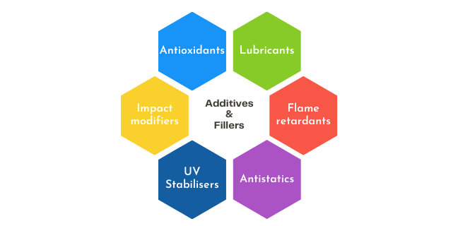
Although the add-ons such as mould release agents, fillers and reinforcements (as shown in the image below) are added to improve some of the properties of injection moulding materials, the side effect is that it changes some other properties like flexural modulus. For example, silicone tends to negatively affect the clamp load as it reduces the drive torque.
Thermal expansion rate
Any substance will expand or contract when subjected to temperature fluctuation. This can result in considerable changes in size, warpage of parts, or internal tension. The stress/strain curve for thermoplastics varies a lot with temperature. When exposed to the same temperature, plastics expand faster than metals. If the clamped material combinations are different, then their expansion rate would be different too. This would make the clamping load fluctuate with temperature.

The material property of the Linear Coefficient of Thermal Expansion (Shown above) is the property to look out for when designing with dissimilar materials. This quantifies a plastic's tendency to expand as temperature rises.
Creep rate
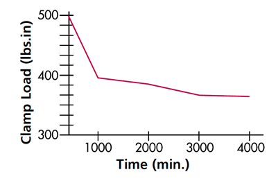
All polymers will creep or irreversibly distort when subjected to long term stress or heat. This creep will result in a loss of clamp load. The graph shows a standard self-tapping screw for plastic losing clamping load over time.
The following methods reduce the creep effects in a joint
-
- Reduce bearing surface stress by
- Increasing the head diameter or using a larger washer to distribute the load
- Reducing the clearance hole diameter to increase clamping surface area
- Reducing initial clamp load at assembly
- Include spring elements such as a spring and flat washer to the joint to absorb the creep
- Include a metal sleeve in the clamped component to reduce the load on plastic
- Increase material stiffness
- Reduce bearing surface stress by
Types of screws
Selecting the correct threaded fastener (self-tapping screw) to suit the material is critical as it directly impacts drive to strip torque ratio and clamping retention. The table under section material stiffness should give a starting point in screw selection using the material stiffness.
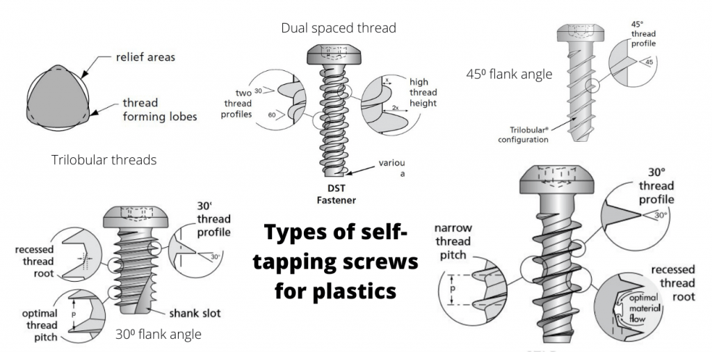
Thread forming and thread cutting screws are available in flank angles of 30⁰, 40⁰, 45⁰, 48⁰ & 60⁰. Some brands also do dual spaced threads and trilobular shapes.
- 30⁰ flank angle – A 30 degree round single start thread forming screw with a reduced core and wide thread pitch for high performance in most thermoplastics and some thermosets
- 45⁰ flank angle with trilobular threads – A trilobular bodied single start thread forming screw with a 45-degree thread angle designed for installing into a wide variety of thermoplastics including glass-filled Nylons and modified Polyphenylene oxide.
- 60⁰ flank angle with trilobular threads – A trilobular bodied single start thread forming screw with a 60-thread angle designed for standard performance in Nylon, Acetal, ABS, and some glass-filled nylons.
- Thread cutting screws – A 30o & 60o circular thread form with a notched end designed for cutting a thread is used on harder plastics such as thermosets.
- Dual spaced thread – These have both 30⁰ and 60⁰ flank angles with different size diameter threads as shown in the above image.
Fastener interface design
Key product design factors that can influence a fastener's ability to perform satisfactorily are pilot hole diameter, thread engagement, length of engagement and boss design. Though product design may impose certain constraints on these four key factors, laboratory testing will establish the best mix of these parameters for your application. So, you must do some testing on sample plastic material with different screws.
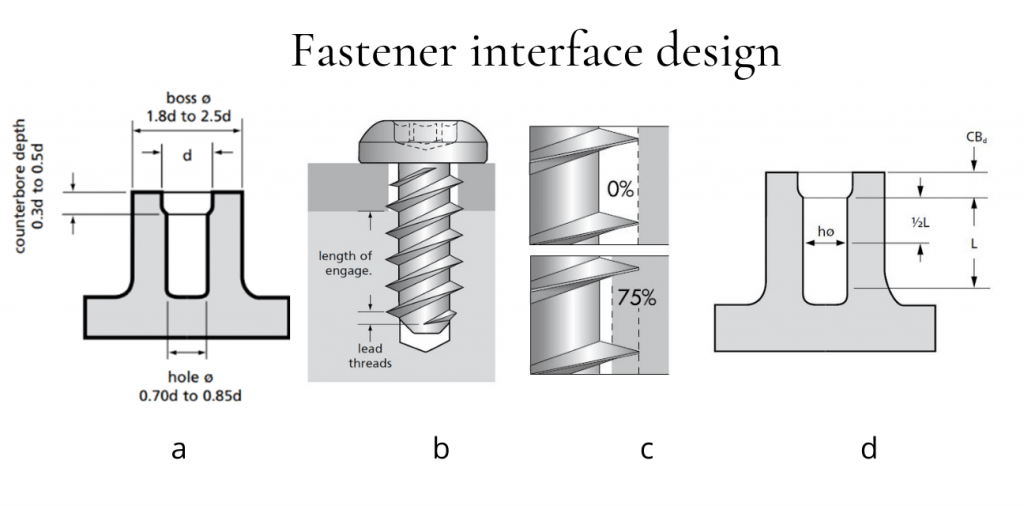
Pilot hole diameter and thread engagement – The pilot hole diameter and the diametrical thread engagement will go hand in hand. The amount of thread flank depth filled by the material is referred to as thread engagement and represented as a percentage. Never use 100% thread engagement as it will increase the torque required and does not improve the joint performance. As a rule of thumb, 75%-80% of thread engagement is used on stiff materials to achieve a good joint.
Length of engagement – The engagement length is the distance between full-sized fastening threads and the nut material. The screw engagement length is specified as a factor of the nominal screw diameter and should range between 2 and 2.5 times the screw diameter.
Boss design – Drafted holes are required to injection mould thermoplastic, but they reduce thread engagement due to the diameter changing along the screw length. To maintain proper mould operation, always use the least amount of draft angle feasible. In general, the nominal hole size is measured at a depth equal to half of the entire length of engagement of the fastener, excluding the counterbore. Generally, screw manufacturers define the pilot hole and boss dimensions for their self-tapping screws.
Screw joint performance
Strip-To-Drive Ratio
The strip-to-drive ratio, which is the ratio of stripping torque to driving torque, is used to determine the production feasibility of a fastener joint. This ratio should be around 5:1 for high-volume manufacturing with power tools. A 2:1 ratio may be acceptable with well-trained employees using consistent components and hand tools. Lubricants will dramatically reduce this ratio, hence should be avoided.
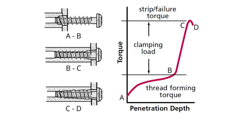
The torque-turn graph above shows how a self-tapping screw behaves to the torque applied. Driving torque somewhat linearly increases up to "B" which cuts a thread and overcome thread sliding friction along with the thread depth. The screw head contacts the top material (plastic or metal) at "B." Any further torque transfers into compressive loading of the threads up to "C," the stripping torque. Stress in the threads approaches the yield point of the plastic at "C," and the threads begin to shear off. When the threads strips fully, the threads continue to strip off to point "D."
Stripping Torque
Since plastics are softer than metal, the threads can be easily stripped while tightening the screw. Stripping torque of screws for plastic can be calculated using the formula below for a given pulling out force F.
| Stripping Torque | |
|---|---|
| \(T = Fr (f_1 + f_2 + \frac{p}{2\pi r}) \) | |
| \(T\) | Torque to develop pull-out force |
| \(r\) | Pitch radius of screw (Dp/2) |
| \({D_{p}}\) | pitch diameter |
| \(p\) | Thread pitch |
| \(F\) | Pull-out force |
| \({f_{1}}\) | Coefficient of friction screw plastic |
| \({f_{2}}\) | Coefficient of friction screwhead – material underneath |
Pull out Force
Pull out force will depend on the diameter of the screw, length of engagement and shear stress of the material. Pull out force can be calculated using the following formula.
| Pull out force | |
|---|---|
| \(F = \frac{\tau \pi {D_p}L}{S}\) | |
| \(F\) | Pull out force |
| \(\tau \) | Shear stress (\(\tau = \frac{{\sigma _t}}{\sqrt{}3}\) ) |
| \(\sigma \) | Tensile yield stress or design stress |
| \({D_{p}}\) | Pitch diameter |
| \(L\) | Axial length of full thread engagement |
| \(S\) | safety factor (\(S = 1.2 {{c _1}}.{c_2}\) ) |
| \({c_{1}}\) | 1,0 for special screws 1,5 for ordinary screws |
| \({c_{2}}\) | \(c_2 = \frac{10}{{\varepsilon _{br}}} (\geq 1.0)\) |
| \({\varepsilon _{br}}\) | elongation at break, (%) |
General tips
The following principles should be considered when specifying a plastic fastener to have a successful joint.
- All pilot holes should be chamfered to the thread major diameter to prevent cracking. Or ideally, have a counterbore part at the start.
- Boss heights should be constructed so that there is no gap between the top of the boss and the component being clamped.
- Boss diameters should be approximately 2.5 to 3 times the diameter of the pilot hole.
- The stripping torque to tapping torque ratio should be at least 3-1 or around 5-1 for automated high volume manufacturing
- Pilot holes should have a threaded engagement of at least twice the screw diameter.
- If there is any uncertainty regarding the applicability, specific application testing should be performed.
Source: https://engineeringproductdesign.com/knowledge-base/self-tapping-screws-for-plastics/
0 Response to "Is It Easy to Work on M3 Self"
Post a Comment